25+ closed loop control system examples with block diagram
Electrical relays are commonly used for switching signals radio frequencies high current circuits when using a lower current circuit and loads such as resistive motor lamp inductive. At present the control system plays an essential role in modern technology because these systems will affect our daily lifeless or more.
Solved Find The Error Transfer Function E S R S Of The System Whose Block Diagram Is Given What Should K Be For The Steady State Error To Be Course Hero
This is a simplified control circuit diagram for the DSC Series.
. Introduction to control systems 1. Closed loop systems the theory of classical PID and the effects of tuning a closed loop control system are discussed in this paper. Then eliminating two loops results in Figure 3-43b.
The system can utilize either R-22 or R-134a which allows for conversion from R-22 to R-134a if needed. First move the branch point of the path involving HI outside the loop involving H as shown in Figure 3-43a. Simplify the block diagram shown in Figure 3-13.
A relay is an electronically operated switch that is remotely activated by an electromagnet which pulls a set of contacts to either make or break a circuit. Top 5 Control Engineering articles April 25 to May 1 2022. The Motor Control Library is a collection of functions that you can use as building blocks for implementing Field Oriented Control FOC of 3-phase motor control applications on dsPIC Digital Signal Controllers DSCs.
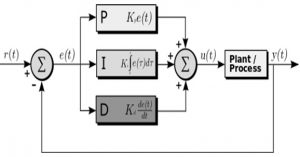
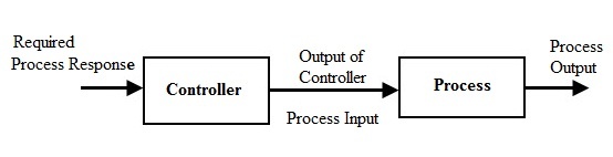
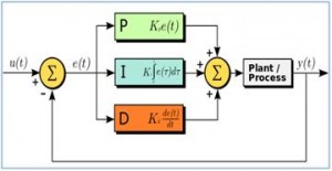
PID controller design using Simulink MATLAB. In closed-loop control the control action from the controller is dependent on the process output. As the name suggests PID algorithm consists of three basic coefficients.
The PID toolset in LabVIEW and the ease of use of these VIs is also. Whereas positive feedback tends to lead to instability via exponential growth oscillation or chaotic behavior negative. An elevator control system is an example of sequence control.
Lets now move towards a simple example regarding the working of a simple PID controller using Simulink. Implemented ability to prevent diagram fonts text formats scaling when the diagram is being scaled. The library functions are designed to be used within any application framework to create high-performance memory-efficient and flexible motor control.
The unit has a microprocessor to control the system. Often based on system logic that involves system states. Combining two blocks into one gives Figure 3-33c.
Closed-loop feedback control with the OnOff function was the cheapest control system and offered a rise time of 15s. Single Starter Relay Car Starter Wiring Diagram. The first control system was invented by James Watts Flyball governor in the year 17.
Open loop control System. State the type of control typically used and explain why it is used Identify and describe. Automatic washing machine Immersion rod.
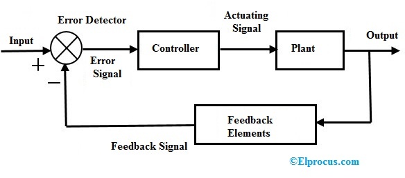
4 What is open loop and control loop systems. A closed-loop control system is a system in which control action is dependent on the desired. Cutaway view showing the refrigeration cycle.
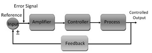
Closed loop control System. You can see we use a TRIAC to control the voltage. Simplify the block diagram shown in Figure 3-42.
Using HFC-134a 200 through 530 nominal tons. Changing the speed of the car is one of the best examples. Negative feedback or balancing feedback occurs when some function of the output of a system process or mechanism is fed back in a manner that tends to reduce the fluctuations in the output whether caused by changes in the input or by other disturbances.
Fortunately this is unlikely if the inner loop is inherently faster than the outer loop or the tuning forces it to be. The main intention of this device is to maintain the engine speed constant by changing the steam supply to the engine. Proportional integral and derivative which are varied to get optimal response.
A new method EnableScalingFonts added to CBCGPVisualContainer class. In addition CBCGPGlobalUtilsScaleByDPICBCGPVisualContainer container has a new optional parameter bScaleFonts TRUE by default. The summing point can either add signals together in which a Plus symbol is used showing the device to be a summer used for positive feedback or it can subtract signals from each other in which case a Minus symbol is used.
8212017 1 Hareesha N G Dept of Aero Engg DSCE Blore 2. Ii Block diagram of PI closed-loop feedback control Phatthanakun et al. Using HCFC-22 300 to 600 nominal tons.
We also use a half-wave rectifier. The best examples of control systems are. It is used in a continuous feedback loop in order to maintain the speed accuracy at 1 or less.
Concept of automatic controls Open loop and closed loop systems Concepts of feedback systems Requirements of an ideal control system Types of controllers Proportional Integral Proportional Integral Proportional Integral Differential controllers. The PTC polymer-based heating element takes 5 min to reach the set temperature of 615 64 and holds up to 25 min. The two controllers might compete with each other to the point of driving the closed-loop system unstable.
For anyone thats interested this is the control circuit diagram with more details. The block diagram of a simple PID controller is provided in the figure below Figure 2. Differentiate feedback and feedforward control loops in terms of their operation design benefits and limitations Perform the following functions for each type of standard process control loop ie pressure flow level and temperature.
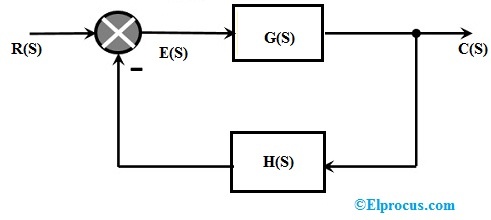
The symbol used to represent a summing point in closed-loop systems block-diagram is that of a circle with two crossed lines as shown. A block diagram of a PID controller in a feedback loop rt is the desired process value or set point. The experimental setup was designed to ensure a constant reverse-bias voltage across the photodiode control the temperature of the detector block light from reaching the detector and establish an electrical path between the detector and the Keithley 6487 ammeter that isolated the measured current from extraneous electromagnetic interference.
An open-loop control system is a system in which the control action is independent of the desired output signalExamples. Cascade control block diagram.
Closed Loop Control System Block Diagram Types Its Applications
What Is A Computer What Is The Block Diagram Of A Computer With A Near Sketch Quora
Why Is Unity Feedback System Better Than Gain Feedback System Quora

Pdf Pso Tuned Pid Controller For Controlling Camera Position In Uav Using 2 Axis Gimbal
Solved Find The Error Transfer Function E S R S Of The System Whose Block Diagram Is Given What Should K Be For The Steady State Error To Be Course Hero
2
Open Loop Closed Loop Control System And Their Differences
Solene
What Is A Computer What Is The Block Diagram Of A Computer With A Near Sketch Quora
Closed Loop Control System Block Diagram Types Its Applications
Pid Controller Working Types Advantages Its Applications
Open Loop Closed Loop Control System And Their Differences

Understanding A Process Control Loop Process Control Control Engineering Studying Math

Open Loop Closed Loop Control System And Their Differences
Pid Controller Working Types Advantages Its Applications

Pdf Pso Tuned Pid Controller For Controlling Camera Position In Uav Using 2 Axis Gimbal

Block Diagram Of Closed Loop Control System System Control System Transfer Function